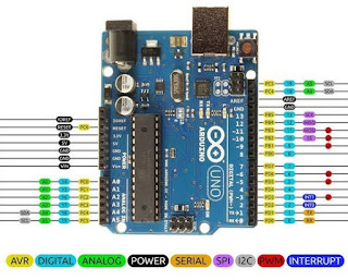
- The arduino uno is a microcontroller board based on the ATmega328.
- Operating voltage 5V.
- Input voltage 7V-12V.(Recommended)
- Input voltage 6V-20V.(Limit)
- DC current per I/O Pin 40mA.
- DC current for 3.3V Pin 50mA.
- Flash memory 32 KB.
- Static random access memory SRAM 2KB.
- Electrically erasable programmable read only memory EEPROM 1KB.
- Lock speed 16 MHz.
 |
PIN Diagram
 |
| Basic Pin layout of Arduino |
- Most of these pins are connected to input/ output device.
- Pin 0 and pin 1 is used to receive Rx and transmit Tx the serial data.
- Pin 2 and pin 3 are external interrupts. These pins can be configured to trigger an interrupt on low value or a change of a value.
- For Pulse width modulation PWM pins 3, 5,6, 9, 10 and 11 are provide 8 bits data or PWM output.
- The UNO has 6 analog inputs, labeled A0-A5, each of these pins provide 10 bits. This means that each pins has 1024 different value.
- RST : reset is as a button which brings the low line of reset the microcontroller. Typically used to add a reset button to shields which block the one on the board.
- AREF : PIN 22, This is used as a reference voltage for the analog inputs.


No comments:
Post a Comment